NFPA 20-2025 11.2.7 covers starting methods for diesel fire pump engines: the engine has a reliable starting device (11.2.7.1), and electric starting (11.2.7.2), hydraulic starting (11.2.7.3) and air starting (11.2.7.4) are each defined. This article covers the air-starting engine and its controller (12.8), clause by clause. For battery starting see diesel engine batteries and charging; for the general diesel controller starting rules see diesel engine starting and control.
In short: used as the only or primary cranking system, the air supply is sized for 180 seconds of continuous cranking without recharging, from two separate, equally sized containers A and B (11.2.7.4.4.2, 11.2.7.4.4.3). The first attempt is automatic from container A for 90 seconds; the second is manual from container B, cranking only while the button is held (11.2.7.4.4.4, 11.2.7.4.4.5). As a secondary system the container is sized for 90 seconds of continuous cranking and the attempt is manual (11.2.7.4.4.6, 11.2.7.4.4.7). High and low air pressure are supervised, and a manual bypass serves control circuit failure (11.2.7.4.4.11, 11.2.7.4.4.12). On the air-starting engine controller the attempt-to-start cycle is a single crank period of approximately 90 seconds (12.8.2(3)).
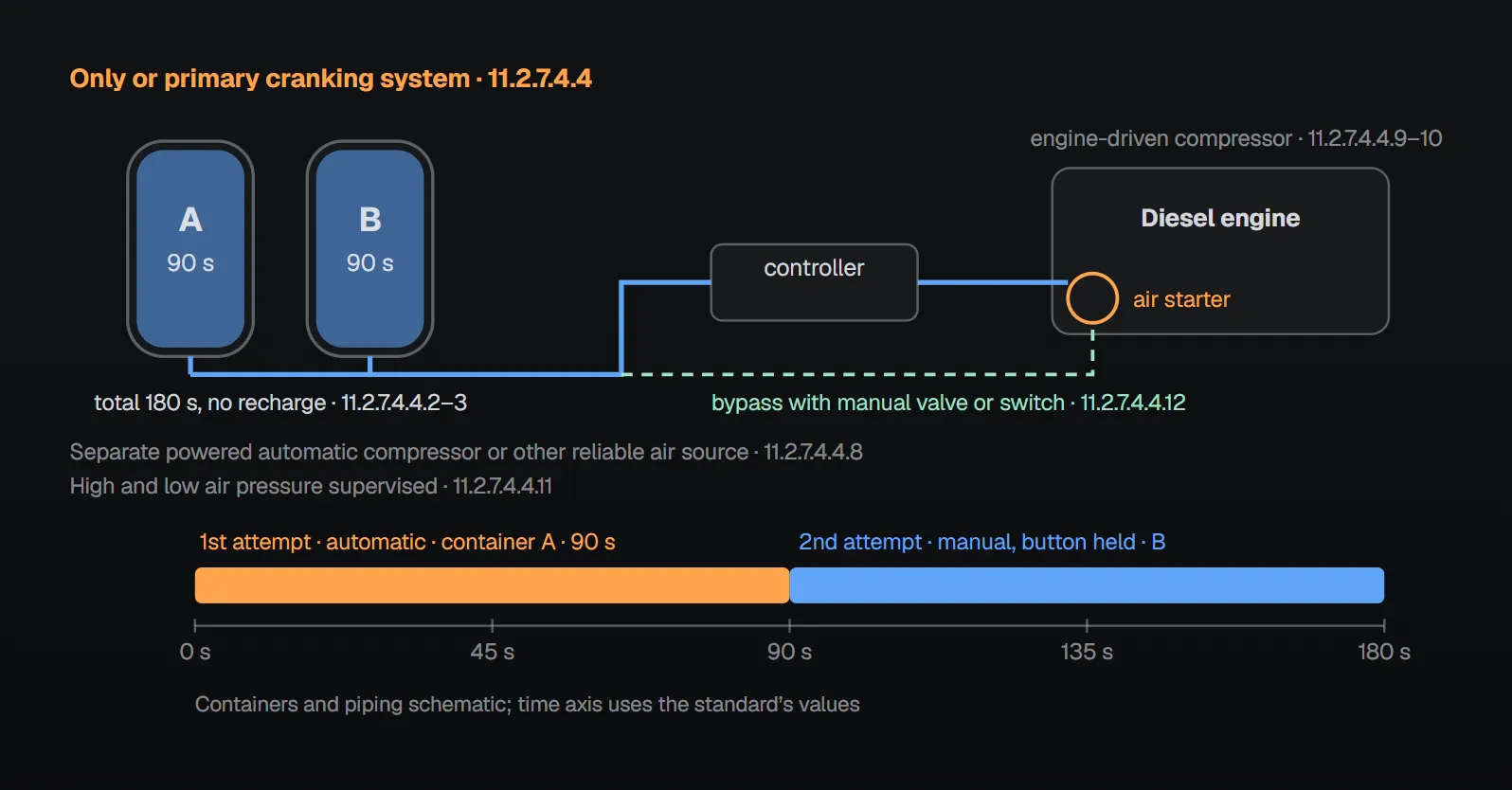
Which rules apply (11.2.7.4.1, 12.8.1)
An air-starting engine follows 11.2.7.4 in addition to 11.1 through 11.2.7.1, 11.2.8 through 11.6.2, 11.6.4 and 11.6.6 (11.2.7.4.1). Its controller follows Section 12.8 in addition to 12.1 through 12.7 (12.8.1). General engine rules are in diesel engine listing and rating.
Factory connections and running signal (11.2.7.4.2, 11.2.7.4.3)
- All conductors for automatic controllers are harnessed or flexibly enclosed, mounted on the engine and connected in an engine junction box to terminals numbered to match the numbered terminals in the controller (11.2.7.4.2.1), so the two sets of terminals can be readily connected in the field (11.2.7.4.2.2).
- The engine has a speed-sensitive switch to signal running and crank termination (11.2.7.4.3.1); power for this signal comes from a source other than the engine compressor (11.2.7.4.3.2).
Air starting supply (11.2.7.4.4)
Where the engine has multiple cranking systems of different types, one is defined as the primary and the other as the secondary cranking system (11.2.7.4.4.1). The rules depend on that role:
| Item | Only or primary system | Secondary system |
|---|---|---|
| Container capacity | 180 seconds of continuous cranking without recharging (11.2.7.4.4.2) | 90 seconds of continuous cranking without recharging (11.2.7.4.4.6) |
| Container arrangement | Total capacity from two separate, equally sized containers A and B (11.2.7.4.4.3) | Number of containers not stated |
| First attempt | Automatic from the signaling source, from container A, with 90 seconds of crank duration (11.2.7.4.4.4) | Start attempt manually activated from engine or controller, cranking only while the button is held (11.2.7.4.4.7) |
| Second attempt | Manual from engine or controller, from container B, cranking only while the button is held (11.2.7.4.4.5) | |
| Engine-driven compressor | An air compressor and a system recharge air compressor driven by the fire pump engine (11.2.7.4.4.9, 11.2.7.4.4.10) | These two clauses are written for the primary system only |
| Separate air source | A separate, powered automatic air compressor or other reliable system supplying air at the required pressure (11.2.7.4.4.8) | |
| Supervision | Suitable supervisory service indicating high and low air pressure (11.2.7.4.4.11) | |
| Control failure | A bypass with a manual valve or switch applying air directly from the container to the starter if the control circuit fails (11.2.7.4.4.12) | |
Annex A.11.2.7.4.4 states that automatic maintenance of air pressure is preferable. Per the NFPA 20 Handbook (2022) commentary, the primary/secondary distinction lets an engine carry a redundant cranking system with a different energy source; for example, an electric starter with batteries A and B as the primary system and a hydraulic or air starting system as the secondary.
Air-starting engine controller (12.8)
- The air supply container, complying with 11.2.7.4.4, is arranged so that manual and automatic starting of the engine can be accomplished (12.8.2(1)).
- If the engine does not start after its attempt-to-start cycle, the controller stops all further cranking and operates the audible and visible fire pump alarms (12.8.2(2)).
- The attempt-to-start cycle is fixed and consists of one crank period of approximately 90 seconds (12.8.2(3)).
| Controller | Attempt-to-start cycle | Clause |
|---|---|---|
| Battery diesel engine controller | Six crank periods of approximately 15 seconds separated by five rest periods of approximately 15 seconds | 12.7.4(5) |
| Air-starting engine controller | One crank period of approximately 90 seconds | 12.8.2(3) |
Manual shutdown uses a stop valve or switch on the controller panel or on the outside of the controller enclosure (12.8.3). The stop valve shuts the engine down through the automatic circuits only after starting causes have returned to normal (12.8.3.1), and this returns the controller to full automatic position (12.8.3.2).
Why (Annex A and Handbook)
- Per the NFPA 20 Handbook (2022) commentary, 12.8.2(1) is intended to match the requirements and ability of battery-cranked engines.
- The single long crank period replaces the 15-second crank-and-rest scheme of battery starting. Per the Handbook, one reason for intermittent cranking is to prevent the electric starter from overheating; an air or hydraulic starter does not generate significant heat while cranking.
- Per the Handbook, air-start fire pump engines are rare; oil field applications are given as an example. Some controllers have one or two purge fittings so the enclosure can be pressurized with instrument air free of flammable vapors; the second one monitors pressure to sound an alarm if it drops too low. This scheme needs a seam-welded Type 4 enclosure strong enough for the pressurization, because all controllers contain spark-producing devices such as relays, contactors, fuses, switches and circuit breakers.
Common field mistakes
- One air container on an only or primary system: 11.2.7.4.4.3 requires two separate, equal containers A and B.
- Containers smaller than 180 seconds: contrary to 11.2.7.4.4.2 for an only or primary system.
- Powering the running signal from the engine compressor: contrary to 11.2.7.4.3.2.
- No air pressure supervision or manual bypass: 11.2.7.4.4.11 and 11.2.7.4.4.12 require both.
- Leaving a battery-engine crank cycle in the controller: an air-starting engine uses a single crank of approximately 90 seconds (12.8.2(3)).
Checklist
- Cranking system role defined: only, primary or secondary (11.2.7.4.4.1).
- Container capacity: 180 seconds with equal A + B (only or primary), 90 seconds (secondary) (11.2.7.4.4.2, 11.2.7.4.4.3, 11.2.7.4.4.6).
- Attempt sequence: A automatic for 90 seconds, B manual while held; secondary manual (11.2.7.4.4.4, 11.2.7.4.4.5, 11.2.7.4.4.7).
- Separate automatic compressor; engine-driven compressor on a primary system (11.2.7.4.4.8 through 11.2.7.4.4.10).
- High/low air pressure supervision and manual bypass (11.2.7.4.4.11, 11.2.7.4.4.12).
- Factory wiring to numbered terminals; speed-sensitive switch with signal power not from the compressor (11.2.7.4.2.1, 11.2.7.4.3.1, 11.2.7.4.3.2).
- Controller: manual and automatic starting, single crank of approximately 90 seconds, alarm on failure, manual shutdown (12.8.2, 12.8.3).
Frequently Asked Questions
How large must the air supply container be?
As the only or primary cranking system, it is sized for 180 seconds of continuous cranking without recharging, provided from two separate, equally sized containers A and B (11.2.7.4.4.2, 11.2.7.4.4.3). As a secondary system it is sized for 90 seconds of continuous cranking (11.2.7.4.4.6).
In what order are the air starting attempts made?
On an only or primary system the first attempt is automatic from the signaling source, from container A, with 90 seconds of crank duration; the second is manual from engine or controller, from container B, cranking only while the button is held (11.2.7.4.4.4, 11.2.7.4.4.5). On a secondary system the attempt is manual (11.2.7.4.4.7).
Is the controller crank cycle different from a battery engine?
Yes. On an air-starting engine controller the cycle is fixed at one crank period of approximately 90 seconds (12.8.2(3)); a battery engine controller uses six cranks of approximately 15 seconds with five rests (12.7.4(5)). NFPA 20 Handbook (2022): an air starter does not generate significant heat while cranking.
What air compressors are required?
A separate, powered automatic air compressor or another reliable system supplying air at the required pressure (11.2.7.4.4.8); a primary system also has a compressor driven by the fire pump engine (11.2.7.4.4.9, 11.2.7.4.4.10). Annex A.11.2.7.4.4 prefers automatic maintenance of air pressure.
How is the engine started if the control circuit fails?
A bypass with a manual valve or switch applies air directly from the container to the engine starter (11.2.7.4.4.12). High and low air pressure are also supervised (11.2.7.4.4.11).

SprinkCalc — Fire Sprinkler Design Across Three Standards
SprinkCalc covers hazard classification, design density and area, K-factor selection, water demand and hydraulic calculations for NFPA 13, FM Global and BS EN 12845 in a single iOS app, and exports a professional PDF report.
Download SprinkCalc on the App Store
MEP Calc — 110+ Engineering Calculators
MEP Calc bundles 110+ engineering modules in one iOS app: 21 fire calculations plus heating, cooling, HVAC, plumbing, steam and natural gas.
Download MEP Calc on the App StoreNFPA 20-2025, Standard for the Installation of Stationary Pumps for Fire Protection: 11.2.7, 11.2.7.1; 11.2.7.4.1–11.2.7.4.4.12; 12.7.4(5); 12.8.1–12.8.3.2; Annex A.11.2.7.4.4 (explanatory). NFPA 20 Handbook 2022 commentary: 11.2.7.3.12 (primary and secondary cranking systems), Section 12.8.