A diesel fire pump controller starts the engine from its batteries, supervises it and annunciates trouble. NFPA 20-2025 Sections 12.1–12.4 cover its listing, location, construction and indicators. Starting and stopping (12.7) is in the diesel engine starting and control article and battery charging (12.5, 12.6) in the batteries and charging article.
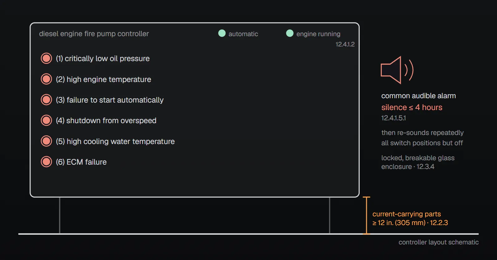
In short: the controller is specifically listed for diesel engine–driven fire pump service and arrives assembled, wired and tested (12.1.3.1, 12.1.3.2). It sits as close as practical to the engine and within sight of it, with current-carrying parts at least 12 in. (305 mm) above the floor (12.2.1, 12.2.3). Six fire pump alarms (12.4.1.3) and fifteen trouble signals (12.4.1.4) use separate indicators and a common audible device, which can be silenced up to 4 hours for alarms and 24 hours for signals (12.4.1.5.1, 12.4.1.5.2). The pressure recorder runs at least 7 days (12.4.4.2).
Listing, location and construction
- The marking shows “Diesel Engine Fire Pump Controller”, the manufacturer’s name, identifying designation, maximum rated pressure, enclosure type and complete electrical rating; where pumps serve different areas each controller carries a sign naming its area (12.1.3.3.1, 12.1.3.3.2). The pump manufacturer arranges the controller manufacturer’s representative where needed during installation, testing and warranty (12.1.4).
- The controller is as close as practical to the engine and within sight of it, located or protected against escaping water, with working clearances per NFPA 70 Article 110 (12.2.1, 12.2.2, 12.2.4). Annex A.12.2.1: if it must be outside the pump room, a glazed wall opening lets the driver and pump be seen during starting, and the pressure control pipeline is protected against freezing and mechanical injury.
- Equipment suits moderately damp locations such as a damp basement and is not impaired by normal dust; equipment not on the engine is mounted on a single noncombustible structure (12.3.1.1, 12.3.1.2, 12.3.2).
- The enclosure is at least NEMA Type 2 dripproof or IP 31, suitably rated outdoors or in special environments, and grounded per NFPA 70 Article 250 (12.3.3.1.1, 12.3.3.1.2, 12.3.3.2). Annex A.12.3.3.1.2: NEMA 3R (IP-34) or NEMA 4 (IP-66) are typical outdoors. Automatic-position switches sit in locked enclosures with breakable glass (12.3.4).
- Controller–engine wiring is stranded, sized for the manufacturer’s currents and protected against mechanical injury (12.3.5.1.1–12.3.5.1.3). The controller is not a junction box, has no interfering external contacts and does not supply jockey pump conductors (12.3.5.3.1–12.3.5.3.3); a remote shutdown or interlock needs AHJ approval (12.3.5.3.3.1). Dampers, oil heaters and other required engine equipment may be powered only through factory dedicated terminals with overcurrent protection (12.3.5.3.4).
- A field connection diagram is permanently attached inside; terminals match it and are commonly numbered with the engine; components carry their schematic symbols and operating instructions are mounted on the controller (12.3.6.1–12.3.6.3, 12.3.7.1, 12.3.8).
Alarms and signals
Visual indication shows that the controller is in automatic and that the engine is running (12.4.1.2). The conditions below are indicated immediately by separate visible indicators and a common audible device heard while the engine runs, operable in all main switch positions except off.
| No. | Fire pump alarm (12.4.1.3) |
|---|---|
| (1) | Critically low oil pressure in the lubrication system |
| (2) | High engine temperature |
| (3) | Failure of engine to start automatically |
| (4) | Shutdown from overspeed |
| (5) | High cooling water temperature |
| (6) | ECM failure |
| No. | Trouble signal (12.4.1.4) | Details |
|---|---|---|
| (1) | Battery failure or missing battery | A separate indicator per battery; initiates at no lower than two-thirds of nominal voltage (8.0 V dc on a 12 V dc system) and when the battery is missing; sensing is delayed |
| (2) | Battery charger failure | A separate indicator per controller; no audible signal required |
| (3) | Low air or hydraulic pressure | With air or hydraulic starting (11.2.7.4, 11.2.7.3), separate indicators for each air supply container and each hydraulic accumulator |
| (4) | System overpressure | For engines with variable-speed pressure-limiting controls, at 115% of set pressure |
| (5) | ECM selector switch in alternate ECM position | Only engines with ECM control |
| (6) | Common alarm for fuel injection malfunction | Only engines with ECM control |
| (7) | Low fuel level | At two-thirds tank capacity |
| (8) | Low engine temperature | — |
| (9) | Interstitial space liquid intrusion | Supervisory signal |
| (10) | Fuel maintenance needed | If an automatic fuel maintenance system is provided |
| (11) | ECM warning | Only engines with ECM control |
| (12) | Low cooling water flow | — |
| (13) | Pressures exceeding those for rated components | — |
| (14) | Low reservoir level | See 12.7.2.7.4 |
| (15) | Lowest permissible suction pressure | See 12.7.2.7.4 |
Annex A.12.4.1.4(1): the battery trip point can be set above two-thirds, but higher than 3/4 of nominal is not recommended, to avoid false signals as batteries age. Annex A.12.4.1.4(6): the type of trouble should be indicated on the engine.
Silencing: a switch or valve separate from the main switch silences the audible device for up to 4 hours for 12.4.1.3 and up to 24 hours for 12.4.1.4; it then re-sounds repeatedly until the condition is corrected or the main switch is turned off (12.4.1.5–12.4.1.5.3). The controller returns to the nonsilenced state when alarms clear, and the audible signal sounds if the switch is left silent while conditions are normal (12.4.1.6, 12.4.1.8).
Remote signals: where the pump room is not constantly attended, audible or visible signals powered by a source other than the starting batteries and not exceeding 125 V are given at a point of constant attendance (12.4.2.1). The remote panel shows engine running and main switch off or manual as separate signals, and controller or engine trouble as separate or common signals, using controller contacts (12.4.2.3, 12.4.3).
Pressure recorder and voltmeter
| Topic | Rule | Paragraph |
|---|---|---|
| Location | A listed device recording each controller’s sensing-line pressure at the controller input | 12.4.4.1 |
| Duration | At least 7 days without reset or rewinding | 12.4.4.2 |
| Surge rating | 400 psi (27.6 bar) or 133% of maximum rated pressure, whichever is higher, without losing accuracy | 12.4.4.3 |
| Power | Spring wound or reliable electric; not solely ac; an electric recorder runs at least 24 hours after ac loss | 12.4.4.4–12.4.4.6 |
| Non-pressure-actuated controller | Recorder not required | 12.4.4.7 |
| Voltmeter | Each battery bank, ±5% accuracy; shows voltage during cranking | 12.4.5 |
Annex A.12.4.4: the recorder should record at least 150% of pump discharge pressure under no-flow conditions (which can exceed 400 psi (27.6 bar) in a high-rise building); one multichannel device can serve several sensors.
Why?
- Stranded wire: per the NFPA 20 Handbook (2022) commentary it better withstands engine vibration and allows ring lugs, so a loose screw may still leave a connection good enough for emergency running.
- No junction box, no jockey supply: the Handbook (2022) says this limits access to a controller that should stay locked and keeps out foreign circuits; a load on the controller’s ac circuit can trip the upstream breaker, leaving the controller without ac and the batteries without a charger.
- Height and glass: per the Handbook (2022), fire-fighting water can collect at low points, so raised parts are less likely to get wet; breakable glass lets an operator switch to manual to start the engine, or turn it off, in an emergency.
Mistakes named in the sources
- Using the controller as a junction box or feeding the jockey pump from it (12.3.5.3.1, 12.3.5.3.3).
- A unit marked only “Fire Pump Controller” but listed as a general industrial panel: the Handbook (2022) says “Diesel Engine Fire Pump Controller” should be on the same nameplate as the listing mark.
- Placing the controller out of sight of the engine (12.2.1).
Checklist
- Is the controller listed for diesel fire pump service and correctly marked? (12.1.3)
- Is it within sight of the engine, protected from water, live parts at least 12 in. (305 mm) up? (12.2)
- Is the enclosure at least NEMA Type 2 or IP 31, with automatic switches behind breakable glass? (12.3.3, 12.3.4)
- Is wiring stranded, with no junction-box use and no jockey supply? (12.3.5)
- Do alarms, signals and the 4 h / 24 h silencing work? (12.4.1)
- Are remote signals at most 125 V; does the recorder run 7 days and 24 hours after ac loss? (12.4.2.1, 12.4.4)
Frequently Asked Questions
Where is a diesel fire pump controller located?
As close as practical to the engine and within sight of it (12.2.1), protected from escaping water (12.2.2), with current-carrying parts at least 12 in. (305 mm) above the floor (12.2.3). If it must be outside the pump room, Annex A.12.2.1 recommends a glazed wall opening.
Which alarms are required at the controller?
The six fire pump alarms of 12.4.1.3: critically low oil pressure, high engine temperature, failure to start automatically, shutdown from overspeed, high cooling water temperature and ECM failure. 12.4.1.4 adds fifteen trouble signals.
At what voltage does the battery failure signal start?
At no lower than two-thirds of nominal voltage, 8.0 V dc on a 12 V dc system (12.4.1.4(1)). Annex A.12.4.1.4(1) advises not setting it above 3/4 of nominal to avoid false signals as batteries age.
How long can controller alarms be silenced?
Up to 4 hours for 12.4.1.3 alarms and up to 24 hours for 12.4.1.4 signals, then they re-sound repeatedly (12.4.1.5.1, 12.4.1.5.2). When the condition clears the controller returns to the nonsilenced state (12.4.1.6).
Can the jockey pump be fed from the diesel controller?
No. Jockey pump supply conductors are not connected to the diesel controller, and the controller is not used as a junction box (12.3.5.3.1, 12.3.5.3.3).

SprinkCalc — Fire Sprinkler Design Across Three Standards
SprinkCalc covers hazard classification, design density and area, K-factor selection, water demand and hydraulic calculations for NFPA 13, FM Global and BS EN 12845 in a single iOS app, and exports a professional PDF report.
Download SprinkCalc on the App Store
MEP Calc — 110+ Engineering Calculators
MEP Calc bundles 110+ engineering modules in one iOS app: 21 fire calculations plus heating, cooling, HVAC, plumbing, steam and natural gas.
Download MEP Calc on the App StoreNFPA 20-2025, Standard for the Installation of Stationary Pumps for Fire Protection: 12.1.1–12.1.4; 12.2.1–12.2.4; 12.3.1.1–12.3.8; 12.4.1.1–12.4.1.8; 12.4.2.1–12.4.2.3; 12.4.3; 12.4.4.1–12.4.4.7; 12.4.5; Annex A.12.2.1, A.12.3.3.1.2, A.12.4.1.4(1), A.12.4.1.4(6), A.12.4.4 (explanatory). NFPA 20 Handbook 2022 commentary: Sections 12.1–12.4.