When does an electric fire pump controller start the pump, who may stop the motor, and when is automatic shutdown allowed? NFPA 20-2025 answers these questions in Section 10.5. This article goes through the starting and stopping rules clause by clause, with the reasoning from Annex A and the NFPA 20 Handbook (2022) commentary. Sensing line piping is covered in fire pump pressure sensing line, and the isolating switch, circuit breaker and indicators in fire pump controller components.
In short: an automatic controller is self-acting to start, run and protect the motor, and is also operable as a nonautomatic controller (10.5.1.1, 10.5.1.3). Starting begins on a pressure drop or on the opening of a remote contact (10.5.1.2). A remote station cannot stop the motor, except a momentary station installed within sight of the controller (10.5.2.4.1, 10.5.2.4.2). Multiple pumps do not start together but at 5 to 10 second intervals (10.5.2.5.1, 10.5.2.5.3). Automatic shutdown after automatic start is allowed only during automatic testing or where approved by the AHJ, with a minimum run timer of at least 10 minutes (10.5.4.2.1, 10.5.4.2.2).
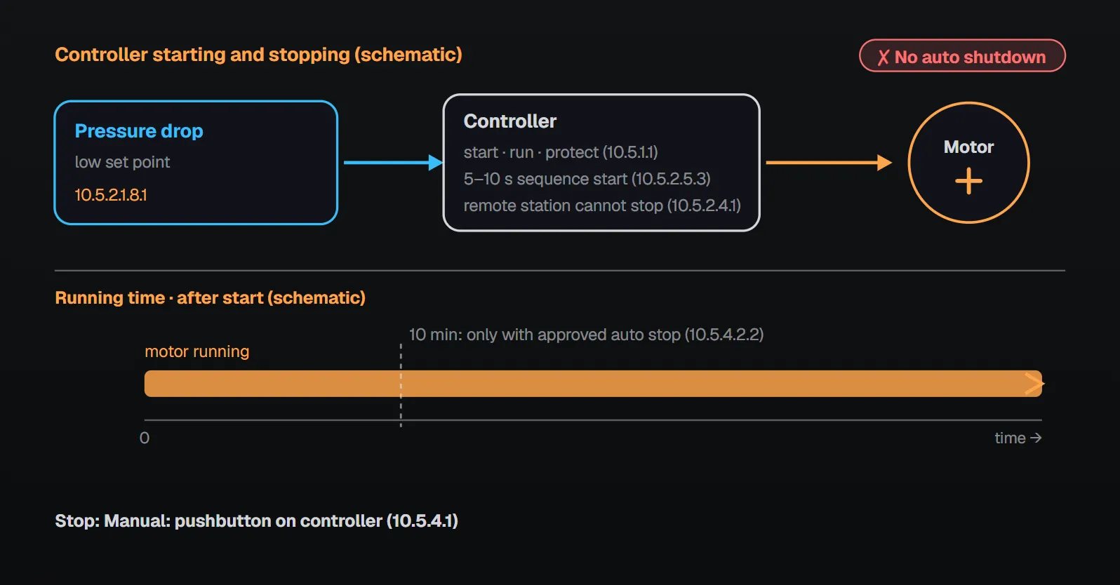
Automatic and nonautomatic controllers (10.5.1)
Annex A.10.5.1 takes its definitions from NFPA 70: automatic means self-acting, operating by its own mechanism when actuated by an impersonal influence such as a change in current, pressure, temperature or mechanical configuration; nonautomatic means requiring personal intervention, which does not necessarily imply a manual controller. An automatic controller starts on a pressure switch or a nonpressure switch (10.5.1.2) and is also operable as a nonautomatic controller (10.5.1.3). A nonautomatic controller is actuated by manually initiated electrical means and manually initiated mechanical means (10.5.1.4). Per the Handbook (2022), the electrical means is the local start pushbutton and the mechanical means is the emergency-run handle.
Water pressure control (10.5.2.1)
| Rule | Clause |
|---|---|
| A pressure-actuated switch or electronic pressure sensor with adjustable high and low set points, as part of the controller | 10.5.2.1.1.1 |
| At the low setting it initiates the starting sequence if the pump is not already running | 10.5.2.1.8.1 |
| The sensing device withstands a momentary surge of 400 psi (27.6 bar) or 133 percent of the controller’s maximum rated pressure, whichever is higher, without losing accuracy | 10.5.2.1.6 |
| An electronic sensor is monitored during automatic testing; on a solenoid drain valve start, a reading above the higher of 10 psi (0.68 bar) and 3.33 percent of the maximum rated pressure gives a visual and audible signal that can be silenced | 10.5.2.1.3, 10.5.2.1.3.1 |
| Signal when sensor output is below 10 percent of rated span or below its rated zero output, or the reading is more than 10 percent above rated full-scale output | 10.5.2.1.3.2 |
| Pressure recorder stores events for at least 7 days; its data are accessed without opening the controller or taking it out of service | 10.5.2.1.8.4, 10.5.2.1.8.7 |
Per Annex A.10.5.2.1.3, sensor monitoring is meant to catch a transducer that has drifted upward from zero over time; one that drifts downward starts the pump anyway. Per the Handbook (2022), an upward-drifting sensor might not sense the pressure drop when a sprinkler opens in a fire, so the pump might not start. Per Annex A.10.5.2.1.3.1, while the solenoid drain valve is open the restricting orifice keeps the transducer pressure near zero; that is when it can be verified to read less than 10 psi. Per Annex A.10.5.2.1.8.2, the recorder should record at least 150 percent of the pump discharge pressure at no flow. Line and orifice rules: fire pump pressure sensing line.
Nonpressure switch controllers and special equipment (10.5.2.2, 10.5.2.3)
A nonpressure switch–actuated automatic controller starts on the automatic opening of remote contact(s), and no pressure-sensing device is required (10.5.2.2.1, 10.5.2.2.2). In this controller nothing but the means on the controller can stop the motor (10.5.2.2.3). Where the pump supplies special water control equipment such as deluge or dry pipe valves, the motor may be started on operation of that equipment before the pressure device would do so; starting is initiated by opening the control circuit loop containing the equipment (10.5.2.3.1–10.5.2.3.3). Per the Handbook (2022), starting on loop opening lets the pump start even if a conductor breaks or is disconnected, and banning remote stop switches keeps a broken or shorted switch wire from disabling the pump permanently.
Remote stations and sequence starting (10.5.2.4, 10.5.2.5)
Where remote control stations provide nonautomatic continuous operation independent of the pressure switch, they cannot stop the motor (10.5.2.4.1). A remote momentary station may include a stop if it is within sight of the controller (10.5.2.4.2). Per the Handbook (2022), remote stopping is undesirable because it is hard to tell from afar whether all fires are out; the within-sight permission came in the 2019 edition because of arc flash hazards.
| Multiple pumps | Clause |
|---|---|
| Each controller has a sequential timing device so no driver starts simultaneously with another | 10.5.2.5.1 |
| A pump supplying suction pressure to another starts within 10 seconds before the pump it supplies | 10.5.2.5.2 |
| Where more than one pump must run, they start at intervals of 5 to 10 seconds | 10.5.2.5.3 |
| Failure of a leading driver to start does not prevent the next units from starting | 10.5.2.5.4 |
Per the Handbook (2022), sequencing parallel pumps limits starting current, voltage drop and hydraulic stress; in series, the feeding pump starts first so the higher zone pump does not run and cavitate without enough suction pressure. Series arrangements: fire pumps arranged in series.
External circuits (10.5.2.6)
An open, ground-fault or short circuit in any control circuit extending outside the pump room does not prevent the pump from operating by all other internal or external means (10.5.2.6.1). Such faults may cause continuous running but cannot stop the controller from starting for other causes (10.5.2.6.2). Control conductors in the pump room that are not fault tolerant are protected against mechanical injury (10.5.2.6.3).
Automatic testing and automatic remote testing (10.5.2.7, 10.5.2.8)
- The controller starts, runs and shuts down the motor at the minimum test frequency and duration required by NFPA 25; the test shows as a pressure drop on the recorder and is initiated by a solenoid drain valve on the pressure control line (10.5.2.7.1–10.5.2.7.3).
- If no other starting or running cause exists, the motor shuts down at least on overload, reversed phase rotation, single phasing, overpressure, leak detection, low reservoir level and lowest permissible suction pressure (10.5.2.7.4); the last two need not shut it down during no-flow testing (10.5.2.7.4.1).
- If a starting cause occurs after such a shutdown, the controller restarts the motor regardless of those conditions (10.5.2.7.5). Per Annex A.10.5.2.7.5, a starting cause is a pressure drop, a deluge valve contact opening, a remote start signal or a manual pushbutton start.
- If another starting cause occurs during the test, the test ends, the controller returns to automatic operation and signals (10.5.2.7.7). A local means cancels all automatic testing, and failure to start from automatic mode gives a visible and audible alarm (10.5.2.7.10, 10.5.2.7.12).
- Remote testing over a network uses an authorized user’s cybersecure connection and the equipment is evaluated for cybersecurity; a locally wired system needs no such evaluation (10.5.2.8.1, 10.5.2.8.1.1, 10.5.2.8.2). Remote stop is allowed only during the test sequence; on loss of connectivity, and in any case after 30 minutes, the controller ends testing and returns to standby (10.5.2.8.4–10.5.2.8.6).
Per Annex A.10.5.2.8.5, because monitoring matters during a remote test, on loss of connectivity the minimum run timer should be overridden, the pump stopped and valves and test equipment reset to standby. General automatic testing: automated inspection, testing and monitoring.
Manual and emergency-run mechanical control (10.5.3)
- A manually operated switch on the control panel; a manually started motor is not affected by the pressure device and runs until manually shut down (10.5.3.1.1, 10.5.3.1.2).
- An emergency-run handle or lever mechanically closes the motor-circuit switching mechanism and gives continuous running independent of electric control circuits and of the pressure switch (10.5.3.2.1, 10.5.3.2.1.1).
- The handle is mechanically latched or held in the actuated position; latching may be automatic or manual (10.5.3.2.1.2, 10.5.3.2.1.3).
- The handle moves in one direction only from off to final position; released anywhere but full running, the starter returns to off; the handle is marked for function (10.5.3.2.2–10.5.3.2.4).
- The controller can start the motor by opening the solenoid drain valve when the operator initiates it (manual test of automatic operation) (10.5.3.3.1).
Per Annex A.10.5.3.2, the handle is for emergency use when normal electric/magnetic operation of the contactor is not possible; used on reduced-voltage starting controllers, the 15 percent voltage drop limit of Section 9.4 does not apply (see voltage drop). Per the Handbook (2022), latching keeps water pressure from dropping and returning while fire fighters work hose lines, and the circuit breaker rather than the handle is the preferred way to stop the motor.
Methods of stopping (10.5.4)
Manual shutdown is by a pushbutton outside the controller enclosure, which on automatic controllers returns the controller to full automatic (10.5.4.1). Automatic shutdown is not permitted while starting and running causes are present (10.5.4.2). It is permitted only during automatic testing per 10.5.2.7 or where approved by the AHJ (10.5.4.2.1), and then a minimum run timer set for at least 10 minutes is used (10.5.4.2.2). Annex A.10.5.4.2.1(1) notes that even during testing, 4.3.1 requires qualified persons to monitor conditions while the pump runs. Per the Handbook (2022), the timer prevents rapid stops and starts on small demands and lets the motor fan cool the windings.
Common field mistakes
- Setting the controller for automatic stop: contrary to 10.5.4.2.1 outside automatic testing or AHJ approval.
- A remote stop button out of sight of the controller: contrary to 10.5.2.4.1 and 10.5.2.4.2.
- A valve or snubber ahead of the sensing device: prohibited by 10.5.2.1.2 and 10.5.2.1.4.
- Starting pumps simultaneously: 10.5.2.5.1 requires sequential timing.
- Leaving the emergency handle latched and running the pump on the breaker: per the Handbook (2022), this leaves the building without automatic protection.
Checklist
- Sensing device with adjustable set points, surge rating, sensor monitoring signals (10.5.2.1.1.1, 10.5.2.1.3–10.5.2.1.6).
- 7-day recorder, data access without opening the controller (10.5.2.1.8.2–10.5.2.1.8.7).
- Remote stations cannot stop; any stop button within sight of the controller (10.5.2.4).
- Sequence starting 5 to 10 s; feeding pump within 10 s before (10.5.2.5).
- External circuit faults do not prevent starting (10.5.2.6).
- Automatic test, shutdown conditions, 30-minute remote test limit (10.5.2.7, 10.5.2.8).
- Emergency-run handle one-directional, latchable, marked (10.5.3.2).
- Manual stop; automatic stop only under 10.5.4.2.1, timer at least 10 min (10.5.4).
Frequently Asked Questions
Can a fire pump be set for automatic shutdown?
Not while starting and running causes are present (10.5.4.2). Automatic shutdown is allowed only during automatic testing per 10.5.2.7 or where approved by the AHJ, with a minimum run timer set for at least 10 minutes (10.5.4.2.1, 10.5.4.2.2).
Can a remote stop button be installed?
A remote control station cannot stop the motor (10.5.2.4.1). A remote momentary station may include a stop if it is within sight of the controller (10.5.2.4.2). During automatic remote testing, remote stop is allowed only during the test sequence (10.5.2.8.4).
How are multiple fire pumps sequenced?
Each controller has a sequential timing device; pumps start at 5 to 10 second intervals, a pump feeding another starts within 10 seconds before it, and failure of a leading driver does not stop the rest from starting (10.5.2.5.1–10.5.2.5.4).
Why is an electronic pressure sensor monitored?
Per Annex A.10.5.2.1.3, to catch a transducer that drifts upward from zero over time and might miss a pressure drop. On a solenoid drain valve start, a reading above the higher of 10 psi (0.68 bar) and 3.33 percent of the maximum rated pressure gives a signal (10.5.2.1.3.1).
What is the emergency-run mechanical handle for?
It mechanically closes the contactor and runs the motor independent of control circuits and the pressure switch; it moves in one direction and latches in the running position (10.5.3.2.1–10.5.3.2.2). Per Annex A.10.5.3.2, it is for emergency use when normal electric/magnetic operation is not possible.

SprinkCalc — Fire Sprinkler Design Across Three Standards
SprinkCalc covers hazard classification, design density and area, K-factor selection, water demand and hydraulic calculations for NFPA 13, FM Global and BS EN 12845 in a single iOS app, and exports a professional PDF report.
Download SprinkCalc on the App Store
MEP Calc — 110+ Engineering Calculators
MEP Calc bundles 110+ engineering modules in one iOS app: 21 fire calculations plus heating, cooling, HVAC, plumbing, steam and natural gas.
Download MEP Calc on the App StoreNFPA 20-2025, Standard for the Installation of Stationary Pumps for Fire Protection: 4.3.1; 9.4; 10.5.1.1–10.5.1.4; 10.5.2.1.1.1, 10.5.2.1.2, 10.5.2.1.3–10.5.2.1.3.2, 10.5.2.1.4–10.5.2.1.6, 10.5.2.1.8.1–10.5.2.1.8.7; 10.5.2.2.1–10.5.2.2.3; 10.5.2.3.1–10.5.2.3.3; 10.5.2.4.1, 10.5.2.4.2; 10.5.2.5.1–10.5.2.5.4; 10.5.2.6.1–10.5.2.6.3; 10.5.2.7.1–10.5.2.7.12; 10.5.2.8.1–10.5.2.8.6; 10.5.3.1.1–10.5.3.3.1; 10.5.4.1–10.5.4.2.2; Annex A.10.5.1, A.10.5.2.1.3, A.10.5.2.1.3.1, A.10.5.2.1.8.2, A.10.5.2.7.5, A.10.5.2.8.5, A.10.5.3.2, A.10.5.4.2.1(1) (explanatory). NFPA 20 Handbook 2022 commentary: Section 10.5.