The pump that injects concentrate or an additive into the water stream of a foam system is also covered by NFPA 20. The standard gives these pumps their own rules in Section 8.2 and specifies in 8.5.3 where the safety relief valve discharge is piped. This article explains both sections with Annex A and the NFPA 20 Handbook (2022) commentary. For the general positive displacement rules (listing, seals, dump valve) see positive displacement fire pumps.
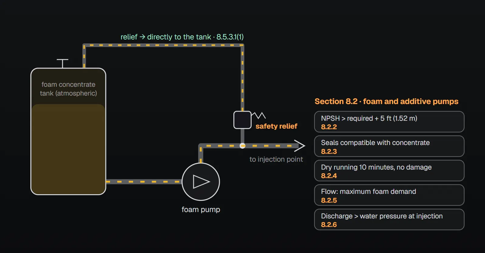
In short: additive pumps meet the requirements for foam concentrate pumps (8.2.1). NPSH exceeds the manufacturer’s required NPSH plus 5 ft (1.52 m) of liquid (8.2.2); seal materials are compatible with the concentrate (8.2.3); foam concentrate pumps can run dry for 10 minutes without damage (8.2.4); flow rates meet the maximum foam flow demand (8.2.5); discharge pressure exceeds the maximum water pressure under any operating condition at the injection point (8.2.6). The safety relief valve is piped to the concentrate tank, to a valve-free tank return line or, if a means to prevent overheating is provided, to pump suction (8.5.3.1); there is no valve between its outlet and its connection to the system (8.5.3.2).
Definition and scope
An additive pump is a pump used to inject additives into the water stream (3.3.52.1); the definition of foam concentrate pump refers to it (3.3.52.6). Per the Handbook (2022) commentary, the requirements of 8.2 apply to any positive displacement pump in a fire protection system that pumps any liquid other than water-only solutions. Additive pumps meet the requirements for foam concentrate pumps (8.2.1).
What the rules say: Section 8.2
| Topic | Rule | Clause | Annex A |
|---|---|---|---|
| NPSH | Available NPSH exceeds the manufacturer’s required NPSH plus 5 ft (1.52 m) of liquid | 8.2.2 | A.8.2.2 |
| Seal materials | Compatible with the foam concentrate or additive | 8.2.3 | — |
| Dry run | Foam concentrate pump, 10 minutes without damage | 8.2.4 | A.8.2.4 |
| Minimum flow rates | Meet the maximum foam flow demand for the intended service | 8.2.5 | A.8.2.5 |
| Discharge pressure | Exceeds the maximum water pressure under any operating condition at the point of foam concentrate injection | 8.2.6 | A.8.2.6 |
NPSH: the 5 ft (1.52 m) margin
Annex A.8.2.2 notes that viscous concentrates and additives have significant pipe friction loss from the supply tank to the pump suction, and that specific flow rates are determined by the applicable NFPA standard. The Handbook (2022) says the 5 ft (1.52 m) margin can be gained by raising the liquid level in the tank, raising the tank bottom above the pump inlet or lowering the pump inlet below the tank bottom. It also gives the pressure-head conversion for liquids other than water: h (ft) = p (psi) × 2.31 / SG and p (bar) = h (m) × SG / 10.197, where SG is specific gravity. For water, see the fire pump NPSH calculator.
Seals and dry running
Per the Handbook, a seal material incompatible with the foam or additive could degrade the seal and leave pump performance inadequate (8.2.3). Positive displacement pumps typically rely on the pumped fluid for lubrication; the 10 minutes of 8.2.4 give the operator time to shut the pump down after the foam or additive tank is depleted, before damage occurs. Per Annex A.8.2.4 this requirement does not apply to water mist pumps.
Flow: concentration and “over demand”
Per the Handbook, the required flow is determined by other NFPA installation standards such as NFPA 11. Annex A.8.2.5 gives the general method: pump capacity is the maximum water flow multiplied by the desired concentration percentage, plus a 10 percent “over demand” so adequate capacity is available under all conditions. The Handbook (2022) calculation example:
| Step | gpm | L/min |
|---|---|---|
| Maximum water flow (system demand) | 1,000 | 3,785 |
| × 3% concentrate | 30 | 114 |
| + 10% over demand | 3 | 11 |
| Required pump capacity | 33 | 125 |
The Handbook adds that 10 percent is not fixed but a guide; the over demand could be upwards of 30 percent if desired.
Discharge pressure
Per Annex A.8.2.6, concentrate pump discharge pressure is generally the maximum water pressure at the injection point plus 25 psi (2 bar). The Handbook explains that the required discharge pressure is based on the foam system’s calculated discharge pressure from standards such as NFPA 11, with an added safety factor to ensure the concentrate enters the system.
Where the safety relief valve discharges (8.5.3)
All positive displacement pumps have a listed safety relief valve; the general rules are in 8.5.2 (see fittings, drivers, controllers and tests). For foam concentrate pumps the safety relief valve is piped in one of the following ways (8.5.3.1):
- Discharge connected to the foam concentrate tank(s) (8.5.3.1(1)).
- Where there is a tank return line, discharge connected to that line leading back to the tank, provided there is no valve of any kind between the relief valve and the foam concentrate tank(s) (8.5.3.1(2)).
- Discharge connected to the pump suction piping if a means to prevent overheating is provided (8.5.3.1(3)).
There is no valve between the outlet of the safety relief valve and its connection to the system (8.5.3.2).
Why
Annex A.8.5.3: only the tank return line and external valves should be used when the outlet line can be closed for more than a few minutes. Running a pump with an integral relief valve against a closed outlet line overheats the pump and causes a foamy discharge once the outlet is reopened. Thermal relief should be considered when the discharge is piped back to suction; overheating and pump damage can occur quickly if the pump runs against a closed outlet and the relief discharge returns to suction.
Handbook (2022): the relief discharge is piped back to the supply so the foam or additive supply is not depleted; the concentrate quantity is based on a specific discharge duration and should not be consumed by relief valve discharge. Routine no-flow tests are frequently run with the relief valve discharging. Piping to the tank return is acceptable, but the system is designed so the relief valve never discharges against a closed valve. If piped to suction, the pump’s suction pressure limit must not be exceeded and a method to prevent overheating should be considered.
The typical schematics in Annex A show both arrangements: Figure A.8.5.2(a) is foam pump piping with relief back to suction, and Figure A.8.5.2(b) with relief to the tank return. The note to Figure A.8.5.2(b) asks for the safety relief valve discharge to return to the concentrate supply tank with no other valve in that pipe section.
Concentrate piping
Foam concentrate or additive piping is of a material that will not corrode in this service, and galvanized pipe is not used for foam concentrate service (4.15.4.1, 4.15.4.2). Details: fire pump pipe and discharge fittings.
Common mistakes (from the sources)
- Relief return into a line that can be shut: prohibited by 8.5.3.1(2) and 8.5.3.2; the Handbook says the relief valve must not discharge against a closed valve.
- Keeping the outlet closed for long with an integral relief valve: per Annex A.8.5.3 the pump overheats and discharges foamy fluid when reopened.
- Relief to suction without overheating protection: 8.5.3.1(3) requires it; Annex A.8.5.3 warns damage can occur quickly.
- Ignoring suction friction with viscous concentrate: Annex A.8.2.2 notes significant friction loss from tank to suction.
Checklist
- Available NPSH exceeds required NPSH plus 5 ft (1.52 m) (8.2.2).
- Seal materials compatible with the concentrate or additive (8.2.3).
- Foam concentrate pump can run dry for 10 minutes without damage (8.2.4).
- Flow meets the maximum foam demand; Annex A.8.2.5 method and over-demand margin applied (8.2.5).
- Discharge pressure exceeds the maximum water pressure at the injection point; generally plus 25 psi (2 bar) per Annex A.8.2.6 (8.2.6).
- Relief discharge by one of the three paths of 8.5.3.1; no valve in the return or at the outlet (8.5.3).
- Concentrate piping of non-corroding material, not galvanized (4.15.4).
Frequently Asked Questions
Do additive pumps have different rules from foam concentrate pumps?
No. Additive pumps meet the requirements for foam concentrate pumps (NFPA 20-2025 8.2.1). Per the Handbook (2022), Section 8.2 applies to any positive displacement pump pumping a liquid other than water-only solutions.
How long must a foam pump be able to run dry?
A foam concentrate pump must be capable of dry running for 10 minutes without damage (8.2.4). The Handbook (2022) says this gives the operator time to stop the pump after the tank is depleted. Per Annex A.8.2.4 it does not apply to water mist pumps.
How is foam concentrate pump capacity determined?
Per Annex A.8.2.5, multiply the maximum water flow by the desired concentration and add a 10 percent over demand. Handbook (2022) example: 1,000 gpm (3,785 L/min) × 3% = 30 gpm (114 L/min), + 3 gpm (11 L/min) = 33 gpm (125 L/min).
Where does a foam pump safety relief valve discharge?
To the concentrate tank, to the tank return line (provided there is no valve of any kind between the relief valve and the tank) or, if a means to prevent overheating is provided, to pump suction (8.5.3.1). No valve between the relief outlet and its connection to the system (8.5.3.2).
What discharge pressure does a foam pump need?
It must exceed the maximum water pressure under any operating condition at the injection point (8.2.6). Per Annex A.8.2.6, 25 psi (2 bar) is generally added to that pressure.

SprinkCalc — Fire Sprinkler Design Across Three Standards
SprinkCalc covers hazard classification, design density and area, K-factor selection, water demand and hydraulic calculations for NFPA 13, FM Global and BS EN 12845 in a single iOS app, and exports a professional PDF report.
Download SprinkCalc on the App Store
MEP Calc — 110+ Engineering Calculators
MEP Calc bundles 110+ engineering modules in one iOS app: 21 fire calculations plus heating, cooling, HVAC, plumbing, steam and natural gas.
Download MEP Calc on the App StoreNFPA 20-2025, Standard for the Installation of Stationary Pumps for Fire Protection: 3.3.52.1, 3.3.52.6, 4.15.4.1, 4.15.4.2, 8.2.1, 8.2.2, 8.2.3, 8.2.4, 8.2.5, 8.2.6, 8.5.3.1, 8.5.3.2; Annex A.8.2.2, A.8.2.4, A.8.2.5, A.8.2.6, A.8.5.3, Figures A.8.5.2(a) and A.8.5.2(b) (explanatory). NFPA 20 Handbook 2022 commentary: Section 8.2 (including calculation examples) and 8.5.3.