NFPA 20 is not limited to centrifugal pumps: the standard also applies to positive displacement pumps of the horizontal or vertical shaft design (1.3.1). Their rules are in Chapter 8. This article covers the general part of that chapter (8.1): definition and types, listing and characteristic curves, seals, materials and the dump valve.
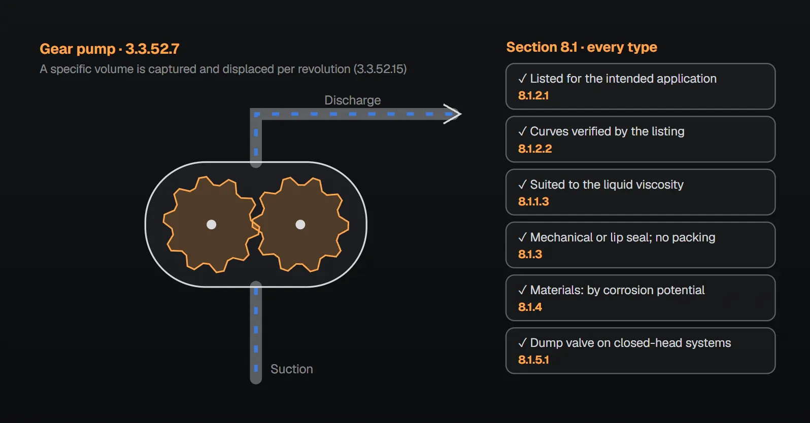
In short: a positive displacement pump produces flow by capturing a specific volume of fluid per pump revolution and reducing the fluid void by a mechanical means (3.3.52.15). The pump is listed for the intended application and the listing verifies the characteristic performance curves of the model (8.1.2.1, 8.1.2.2); the pump is appropriate for the viscosity of the liquid (8.1.1.3). Seals are mechanical or lip seals, and packing is not used (8.1.3). All closed-head systems have a dump valve that bleeds off excess pressure before the driver is subjected to full load (8.1.5.1).
Definition and types
The standard defines a positive displacement pump as a pump that produces flow by capturing a specific volume of fluid per pump revolution and reducing the fluid void by a mechanical means to displace the pumping fluid (3.3.52.15). Chapter 8 applies to pumps that meet this definition (8.1.1). The definitions chapter lists four subtypes:
| Type | How it displaces liquid | Clause |
|---|---|---|
| Gear pump | Gear teeth and casing | 3.3.52.7 |
| Piston plunger pump | A piston or plunger and a cylinder | 3.3.52.14 |
| Rotary lobe pump | Carries fluid between the rotor lobe void and the casing from inlet to outlet | 3.3.52.16 |
| Rotary vane pump | A single rotor with vanes that move with pump rotation to create a void | 3.3.52.17 |
The NFPA 20 Handbook (2022) commentary explains the difference: a centrifugal pump creates pressure by increasing the velocity of the liquid through the rotation of the impeller; a positive displacement pump creates pressure by alternately filling a cavity and then displacing a given volume of liquid. Positive displacement pumps are either rotary or reciprocating; although rotary types rotate like a centrifugal pump, that rotation does not impart energy to the liquid the way a centrifugal pump does. Per the Handbook, the gear pump is the most common type, and these pumps are generally found in water mist and foam-based systems.
What the rules say
Application and the other chapters
- Chapter 8 applies to positive displacement pumps as defined in 3.3.52.15 (8.1.1).
- The provisions of all other chapters apply unless specifically addressed by Chapter 8 (8.1.1.1). Per Annex A.8.1 not all Chapter 4 requirements might apply to these pumps; the Handbook (2022) gives Chapter 8 precedence in a conflict.
- Positive displacement pumps are permitted to pump liquids for fire protection applications (8.1.1.2), and the selected pump is appropriate for the viscosity of the liquid (8.1.1.3). Per the Handbook, each pump’s maximum viscosity is part of its listing; since foam concentrate viscosities vary widely, users refer to the listing.
Listing and characteristic curves
- The positive displacement pump is listed for the intended application (8.1.2.1).
- The listing verifies the characteristic performance curves for a given pump model (8.1.2.2). Per Annex A.8.1.2.2 the curves should be in accordance with ANSI/HI 3.6 (rotary pump tests).
- Annex A.8.1.2 asks for special attention to pump inlet piping size and length.
Seals and materials
- The acceptable seal type is either a mechanical or a lip seal (8.1.3.1); packing is not used (8.1.3.2).
- Pump materials are selected based on the corrosion potential of the environment, the fluids used and operating conditions (8.1.4). Corrosion-resistant material is defined in 3.3.13: brass, copper, stainless steel or other materials that withstand corrosion damage caused by oxidation or other chemical reactions.
Dump valve
- Definition: an automatic valve installed on the discharge side of a positive displacement pump to relieve pressure before the pump driver reaches operating speed (3.3.78.1).
- A dump valve is provided on all closed-head systems so the positive displacement pump can bleed off excess pressure and reach operating speed before the driver is subjected to full load (8.1.5.1).
- The valve operates only for the duration necessary for the pump to reach operating speed (8.1.5.2).
- An electrically operated dump valve is controlled by the positive displacement pump controller (8.1.5.3.1), and means are provided at the controller to ensure dump valve operation during manual start (8.1.5.3.2).
- Dump valves are listed (8.1.5.4). Dump valve discharge is permitted to be piped to the liquid supply tank, pump suction, drain or liquid supply (8.1.5.5).
- Where a diesel driver is used with a positive displacement pump, the diesel controller provides a circuit and timer to actuate and then close the dump valve after engine start is finished (12.7.2.6.4).
Why: Annex A and the Handbook
Materials. Annex A.8.1.4 explains that positive displacement pumps are tolerance dependent, and corrosion can affect pump performance and function.
No packing. The Handbook (2022) explains that packing is designed to leak a small amount of fluid so it stays lubricated. That is not an issue when the fluid is water, as in a centrifugal fire pump, but the leakage is undesirable when the fluid is foam.
Dump valve. According to the Handbook, the driver of a positive displacement pump is not generally sized to overcome the back pressure created if none of the system’s discharge devices have opened during starting; 8.1.5.1 addresses this. Control in the controller lets all pump functions be monitored in one place. The Handbook also states that the requirement originated with the crank cycle of diesel engines trying to start against a pressurized system. The 8.1.5.1 rule applies to all closed-head systems.
Driver power. Per Annex A.4.7.6, maximum brake horsepower of a positive displacement pump typically occurs when the relief valve is flowing 100 percent of rated pump capacity; see fire pump, driver and controller compatibility.
Example: selecting pump and motor from the curve (Annex A.8.1.2.2)
Annex A.8.1.2.2 and Figure A.8.1.2.2 give an example for a foam-water system. After applying appropriate safety factors, the system needs a foam concentrate pump capable of 45 gpm (≈170 L/min) at the maximum system pressure of 230 psi (≈15.9 bar):
- Find 230 psi on the horizontal axis (“differential pressure”) and go vertically to the flow curve that meets 45 gpm. The example pump produces 46 gpm (≈174 L/min) at a standard motor speed designated “rpm-2”.
- On the power curve for the same speed (rpm-2) at 230 psi, read the 13.1 hp (≈9.8 kW) needed to drive the pump.
- An electric motor will be used, so the first available motor rating above this minimum, 15 hp (≈11 kW) at rpm-2, is selected.
The Handbook (2022) states that curves established through the listing and approval tests must be provided by the manufacturer so the designer can select the correct pump. SI values are approximate; the standard gives the example in US units only.
Common mistakes (from the sources)
- A pump with packing: prohibited by 8.1.3.2; the Handbook’s reason is that packing leakage is undesirable with foam.
- No dump valve on a closed-head system: per the Handbook, the driver is not sized to overcome the back pressure when no discharge device is open (8.1.5.1).
- Dump valve discharge to suction without checking suction pressure: a Handbook design alert; 8.1.5.5 permits piping the discharge to suction.
Checklist
- Pump listed for the intended application; characteristic curves verified by the listing (8.1.2.1, 8.1.2.2).
- Liquid viscosity within the pump’s listing (8.1.1.3).
- Pump inlet piping size and length reviewed (A.8.1.2).
- Mechanical or lip seal; no packing (8.1.3).
- Materials selected for the corrosion potential, fluid and operating conditions (8.1.4, 3.3.13).
- Listed dump valve on closed-head systems, operating only until operating speed is reached; if electrically operated, controlled by the pump controller and also working on manual start (8.1.5.1–8.1.5.4, 12.7.2.6.4).
- Dump valve discharge to the supply tank, pump suction, drain or liquid supply; if to suction, suction pressure limits checked (8.1.5.5).
- Pump-specific rules: foam concentrate and additive pumps, water mist system pumps, water mist positive displacement pumping units, fittings, drivers, controllers and tests.
Frequently Asked Questions
What is a positive displacement pump?
A pump that produces flow by capturing a specific volume of fluid per pump revolution and reducing the fluid void by a mechanical means (NFPA 20-2025 3.3.52.15). The standard defines gear, piston plunger, rotary lobe and rotary vane types (3.3.52.7, 3.3.52.14, 3.3.52.16, 3.3.52.17).
How does it differ from a centrifugal pump?
Per the NFPA 20 Handbook (2022) commentary, a centrifugal pump creates pressure by increasing liquid velocity through impeller rotation, while a positive displacement pump fills a cavity and then displaces a given volume. Rotary types rotate but do not impart energy the way a centrifugal pump does.
Can packing be used on a positive displacement fire pump?
No. Seals are mechanical or lip seals and packing is not used (8.1.3.1, 8.1.3.2). The Handbook (2022) explains that packing leaks a small amount to stay lubricated and that this leakage is undesirable with foam.
When is a dump valve required?
On all closed-head systems; it bleeds off excess pressure before the driver takes full load and operates only until the pump reaches operating speed (8.1.5.1, 8.1.5.2). Dump valves are listed (8.1.5.4); with a diesel driver the controller provides a circuit and timer to actuate and close it (12.7.2.6.4).
Do Chapter 4 requirements apply to positive displacement pumps?
The other chapters apply unless Chapter 8 specifically addresses the subject (8.1.1.1). Annex A.8.1 notes that not all Chapter 4 requirements might apply; the Handbook (2022) says Chapter 8 takes precedence in a conflict.

SprinkCalc — Fire Sprinkler Design Across Three Standards
SprinkCalc covers hazard classification, design density and area, K-factor selection, water demand and hydraulic calculations for NFPA 13, FM Global and BS EN 12845 in a single iOS app, and exports a professional PDF report.
Download SprinkCalc on the App Store
MEP Calc — 110+ Engineering Calculators
MEP Calc bundles 110+ engineering modules in one iOS app: 21 fire calculations plus heating, cooling, HVAC, plumbing, steam and natural gas.
Download MEP Calc on the App StoreNFPA 20-2025, Standard for the Installation of Stationary Pumps for Fire Protection: 1.3.1, 3.3.13, 3.3.52.7, 3.3.52.14, 3.3.52.15, 3.3.52.16, 3.3.52.17, 3.3.78.1, 8.1.1, 8.1.1.1, 8.1.1.2, 8.1.1.3, 8.1.2.1, 8.1.2.2, 8.1.3.1, 8.1.3.2, 8.1.4, 8.1.5.1, 8.1.5.2, 8.1.5.3.1, 8.1.5.3.2, 8.1.5.4, 8.1.5.5, 12.7.2.6.4; Annex A.4.7.6, A.8.1, A.8.1.2, A.8.1.2.2 and Figure A.8.1.2.2, A.8.1.4 (explanatory). NFPA 20 Handbook 2022 commentary: Chapter 8 introduction and Section 8.1 (A.8.1, 8.1.1, 8.1.1.3, 8.1.2.2, 8.1.3, 8.1.5 commentary).