NFPA 20-2025 Sections 8.5 to 8.10 cover fittings, drivers, controllers, foundation, coupling and flow test devices for positive displacement (PD) fire pumps. Relief valve piping for foam concentrate pumps (8.5.3) is covered in foam concentrate and additive pumps, and for water mist pumps (8.5.4) in water mist system pumps.
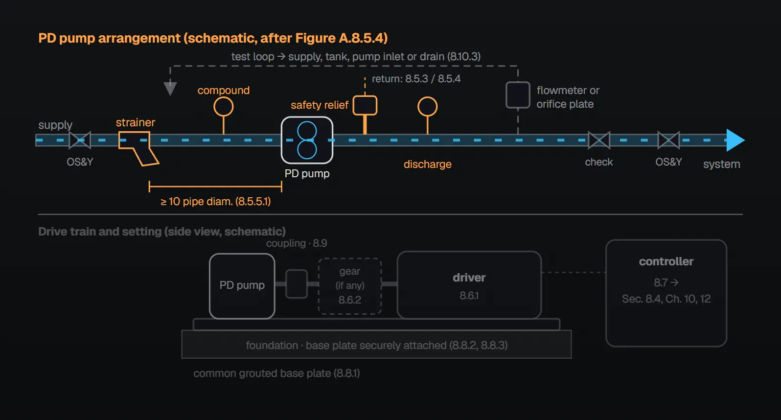
In short: every PD pump has a compound suction gauge and a discharge gauge (8.5.1) and a listed safety relief valve relieving 100 percent of rated capacity at a pressure not exceeding 125 percent of its set pressure (8.5.2.1). The suction strainer is at least 10 pipe diameters from the pump suction inlet, with a net open area at least four times the suction pipe area (8.5.5.1, 8.5.5.3). The primary or standby pump is not used as a jockey pump, except for water mist PD pumping units (8.5.7.1, 8.5.7.2). A reduction gear is listed and bearings are applied for an L10 life of 15,000 hours (8.6.2.1, 8.6.2.3). Pump and driver sit on a common grouted base plate, joined by a listed flexible coupling (8.8.1, 8.9.1). The installation allows testing the pump at rated conditions and the suction supply at maximum flow (8.10.1).
Gauges (8.5.1)
A compound suction gauge and a discharge pressure gauge are furnished (8.5.1). Per the NFPA 20 Handbook (2022) commentary, a compound gauge reads negative and positive pressures; the discharge gauge need not be compound because discharge pressure is assumed never to be negative. Together they show the pressure boost across the pump. For centrifugal pumps see fire pump pressure gauges.
Safety relief valve (8.5.2)
| Rule | Clause |
|---|---|
| Every pump has a listed safety relief valve able to relieve 100 percent of rated capacity at a pressure not exceeding 125 percent of the valve set pressure | 8.5.2.1 |
| Set so that the pressure required to discharge rated capacity is at or below the lowest rated pressure of any component | 8.5.2.2 |
| Installed on the pump discharge to prevent damage to the fire protection system | 8.5.2.3 |
Per Annex A.8.5.2, PD pumps can quickly exceed their maximum design discharge pressure against a closed discharge system; other protective devices such as automatic shutdowns or rupture discs are generally beyond the pump manufacturer’s supply and should be provided by the system designer or user. Per the Handbook (2022), without a relief valve pressure keeps rising until the driver stalls or components fail. Handbook example: for a pump rated 25 gpm (95 L/min) at 50 psi (3.5 bar), the valve is set around 55 psi (3.8 bar) and must relieve at least 25 gpm at no more than 1.25 × 55 = 68.75 psi (1.25 × 3.8 = 4.75 bar). The main relief valve of centrifugal pumps is a separate subject: main relief valve.
Suction strainer (8.5.5)
- A removable, cleanable suction strainer is installed at least 10 pipe diameters from the pump suction inlet (8.5.5.1).
- Strainer pressure drop is calculated to show that sufficient NPSH is available (8.5.5.2).
- Net open area is at least four times the suction pipe area (8.5.5.3).
- Mesh size is based on the liquid viscosity of the concentrate and the pump manufacturer’s recommendation (8.5.5.4).
Per the Handbook (2022), PD pumps are more susceptible than other pump types to damage from debris, so a suction strainer is required for all PD pumps; foam concentrates have a wide range of viscosities to consider in strainer sizing. Per Annex A.8.5.5, the recommended mesh size depends on internal pump tolerances; standard mesh sizes are in Figure A.8.5.5:
| Mesh | 20 | 40 | 60 | 80 | 100 |
|---|---|---|---|---|---|
| Opening (in.) | 0.034 | 0.015 | 0.0092 | 0.007 | 0.0055 |
| Opening (µm) | 860 | 380 | 230 | 190 | 140 |
For centrifugal pump suction screens see suction screen and anti-vortex plate.
Water supply protection (8.5.6)
System design includes protection of potable water supplies and prevention of cross connection or contamination (8.5.6). Per the Handbook (2022), many water purveyors require supply protection where foam or additives are used; the designer plans for backflow prevention, and NFPA 20 permits a backflow prevention device or a break tank (Chapter 4; see fire pump break tank).
Pressure maintenance (8.5.7)
Except as permitted in 8.5.7.2, the primary or standby fire pump is not used as a jockey pump (8.5.7.1; also 4.27.7). Water mist PD pumping units may maintain system pressure under one of these conditions (8.5.7.2):
- The unit is designed and listed to alternate pressure maintenance duty between two or more pumps with variable speed pressure-limiting control.
- The unit is designed and listed to have a redundant pump when one primary pump performs pressure maintenance with variable speed pressure-limiting control.
- The unit is designed to use a dedicated jockey pump not required for primary fire pump service.
In all three cases a supervisory signal is given whenever pressure maintenance is required more than two times in one hour (8.5.7.2). In pressure maintenance mode the unit meets 8.4.9 when the smallest system nozzle discharges at standby pressure (8.5.7.3). A single sensing line may serve the unit controller where the unit also maintains pressure on the water mist system (8.5.7.4).
Per the Handbook (2022), this is permitted because a discrete signal indicates system activation in a fire, and the duty can be rotated from pump to pump. Failure of a redundant motor or dedicated pump does not prevent automatic starting or reduce total capacity. The controller tells pressure maintenance from a fire by the pressure difference, so a single sensing line is enough. Other unit rules: water mist PD pumping units; for centrifugal systems see jockey pump.
Drivers and reduction gears (8.6)
The driver is sized for and has enough power to operate the pump and drive train at all design points (8.6.1). Per Annex A.8.6.1, PD pumps are typically driven by electric motors, internal combustion engines or water motors. Per the Handbook (2022), A.8.6.1 only recognizes water motors and does not make them acceptable drivers: acceptable drivers are listed in 4.7.2 (electric motors, diesel engines, steam turbines or a combination), while a listed water motor–driven PD pump meeting the equivalency provisions of Section 1.5 would comply.
| Item | Rule | Clause |
|---|---|---|
| Reduction gear between driver and pump | Listed for the intended use | 8.6.2.1 |
| Gear standard | ANSI/AGMA 2011-B14 | 8.6.2.1.1 |
| Gears / pinions | AGMA Class 7 or better / AGMA Class 8 or better | 8.6.2.2 |
| Bearings | Per AGMA standards, L10 life of 15,000 hours | 8.6.2.3 |
| Drive with a gear case | Pump manufacturer provides a complete mass elastic system torsional analysis showing no damaging stresses or critical speeds within 25 percent above and below the operating speed of pump(s) and driver | 8.6.2.4 |
| Variable speed drive | Analysis covers all speeds down to 25 percent below the lowest obtainable operating speed | 8.6.2.4.1 |
Per the Handbook (2022), a reduction gear designed improperly or selected on speed change alone can become a failure point and cause loss of the fire pump; running too close to a critical speed can damage the driveline.
A single driver may drive more than one PD pump; redundant pump systems may not share a common driver (8.6.3.1, 8.6.3.2). Details: fire pump, driver and controller compatibility. The Handbook (2022) example rests on NFPA 750 (2019 edition): if two pumps meet demand, four are needed with redundancy, and an electric motor arrangement has at least two motors; 8.6.3.2 prohibits one motor driving all four pumps.
Controllers (8.7)
For PD pump controllers, see Section 8.4 and Chapters 10 and 12 (8.7). Per Annex A.8.7, these controllers can incorporate means for automatic unloading or pressure relief when starting the pump driver.
Foundation and coupling (8.8, 8.9)
- Pump and driver are mounted on a common grouted base plate per the manufacturer’s instructions (8.8.1).
- The base plate is securely attached to a solid foundation so that pump and driver shaft alignment is maintained; the foundation gives solid support (8.8.2, 8.8.3).
- Pump and driver are connected by a listed, closed coupled, flexible coupling or timing gear type of belt drive coupling (8.9.1).
- The coupling transmits the driver horsepower without exceeding the manufacturer’s maximum recommended horsepower and speed (8.9.2).
- Alignment is done after final base plate placement and per the coupling manufacturer’s specifications; the flexible coupling operating angle stays within recommended tolerances (8.9.3–8.9.5).
The standard gives no reasoning for these clauses. For centrifugal pumps see fire pump foundation and coupling alignment.
Flow test devices (8.10)
- The installation allows testing the pump at its rated conditions and the suction supply at the maximum flow available from the pump (8.10.1).
- Additive pumping systems have a flowmeter or orifice plate in a test loop back to the additive supply tank (8.10.2).
- Water pumping systems have a flowmeter or orifice plate in a test loop back to the water supply, tank, inlet side of the water pump, or drain (8.10.3).
Per the Handbook (2022), the suction supply must be testable by flowing liquid from the supply through the pump, not just through a test loop, because foam and additive viscosity can cause significant suction friction loss during a fire. The additive test loop returns to the tank so routine testing does not deplete it.
At acceptance, PD pump flow is tested at a single performance point; the test loop flowmeter reading or discharge pressure is recorded and agrees with the manufacturer’s flow data; with orifice plates, the orifice size and upstream pressure are given to the authority having jurisdiction (14.2.6.6.1–14.2.6.6.4). PD pumps for liquids other than water may be tested with water, with the manufacturer’s viscosity calculations (14.2.6.6.6.1, 14.2.6.6.6.2). For centrifugal pumps see test header and flowmeter.
Common field mistakes
- Strainer right at the pump suction inlet: 8.5.5.1 requires at least 10 pipe diameters.
- Strainer loss left out of the NPSH check: contrary to 8.5.5.2.
- Relief valve set without regard to the lowest-rated component: contrary to 8.5.2.2.
- Primary pump used as a jockey pump: prohibited by 8.5.7.1 outside the 8.5.7.2 conditions for water mist PD units.
- Aligning before the base plate is final: contrary to 8.9.3.
- No means to test the suction supply: 8.10.1 requires testing both the pump and the suction supply.
Checklist
- Compound suction and discharge gauges; listed safety relief: 100 percent flow, ≤ 125 percent of set, on the pump discharge (8.5.1, 8.5.2.1–8.5.2.3).
- Strainer ≥ 10 pipe diameters away, net area ≥ 4× pipe area, NPSH check (8.5.5.1–8.5.5.4).
- Potable water protection; pressure maintenance per 8.5.7 (8.5.6, 8.5.7.2).
- Driver power, listed gear, AGMA classes, L10, torsional analysis (8.6.1–8.6.2.4.1).
- Common grouted base plate, listed coupling, alignment (8.8.1–8.9.5).
- Test loop with flowmeter or orifice plate; suction supply test (8.10.1–8.10.3).
Frequently Asked Questions
Where does the suction strainer go on a PD pump?
At least 10 pipe diameters from the pump suction inlet; it is removable and cleanable, its net open area is at least four times the suction pipe area, and its pressure drop is included in the NPSH check (8.5.5.1–8.5.5.3).
What flow and pressure must the PD pump safety relief valve handle?
A listed valve relieves 100 percent of rated capacity at no more than 125 percent of its set pressure (8.5.2.1); the pressure to discharge rated capacity stays at or below the lowest-rated component (8.5.2.2); the valve is on the pump discharge (8.5.2.3).
Can the primary PD pump act as a jockey pump?
Generally no (8.5.7.1, 4.27.7). Water mist PD pumping units may maintain pressure under one of the three conditions of 8.5.7.2, with a supervisory signal when maintenance is needed more than two times in one hour.
Can a water motor drive a PD fire pump?
Annex A.8.6.1 mentions water motors, but per the Handbook (2022) acceptable drivers are those of 4.7.2; a listed water motor–driven PD pump meeting the equivalency provisions of Section 1.5 would comply.
How is a PD pump tested?
The installation allows testing the pump at rated conditions and the suction supply at maximum flow (8.10.1). Water pumps use a flowmeter or orifice plate in a test loop (8.10.3); at acceptance one performance point is required (14.2.6.6.1, 14.2.6.6.2).

SprinkCalc — Fire Sprinkler Design Across Three Standards
SprinkCalc covers hazard classification, design density and area, K-factor selection, water demand and hydraulic calculations for NFPA 13, FM Global and BS EN 12845 in a single iOS app, and exports a professional PDF report.
Download SprinkCalc on the App Store
MEP Calc — 110+ Engineering Calculators
MEP Calc bundles 110+ engineering modules in one iOS app: 21 fire calculations plus heating, cooling, HVAC, plumbing, steam and natural gas.
Download MEP Calc on the App StoreNFPA 20-2025, Standard for the Installation of Stationary Pumps for Fire Protection: 4.7.2; 4.27.7; 8.5.1, 8.5.2.1–8.5.2.3, 8.5.5.1–8.5.5.4, 8.5.6, 8.5.7.1–8.5.7.4; 8.6.1–8.6.3.2; 8.7; 8.8.1–8.8.3; 8.9.1–8.9.5; 8.10.1–8.10.3; 14.2.6.6.1–14.2.6.6.4, 14.2.6.6.6.1, 14.2.6.6.6.2; Annex A.8.5.2, A.8.5.5 and Figure A.8.5.5, Figure A.8.5.4, A.8.6.1, A.8.7 (explanatory). NFPA 20 Handbook 2022 commentary: Sections 8.5–8.10.