Per the NFPA 20 Handbook (2022) commentary, water mist systems are most commonly supplied by positive displacement pumps. NFPA 20 gives these pumps capacity, NPSH, inlet pressure and excess flow rules in Section 8.3, and specifies in 8.5.4 where the safety relief valve discharges. Water mist positive displacement pumping units, in which several pumps work as one unit, are a separate subject (8.4); see water mist positive displacement pumping units.
In short: positive displacement pumps for water have adequate capacity to meet the maximum system demand for their intended service (8.3.1). NPSH exceeds the manufacturer’s required NPSH plus 5 ft (1.52 m) of liquid (8.3.2), and inlet pressure does not exceed the manufacturer’s recommended maximum (8.3.3). Where pump output can exceed the system flow requirement, a means to relieve the excess flow, such as an unloader valve or orifice, is provided (8.3.4); an unloader valve is in addition to the safety relief valve, not instead of it (8.3.5). The safety relief valve discharges to a drain or to a water supply at atmospheric pressure (8.5.4.1), or into pump suction where two conditions are both met (8.5.4.2).
What the rules say: Section 8.3
Capacity and centrifugal pumps
Positive displacement pumps for water have adequate capacities to meet the maximum system demand for their intended service (8.3.1). Per Annex A.8.3.1, it is not the intent of the standard to prohibit the use of stationary pumps for water mist systems. NFPA 20 Handbook (2022) commentary: a listed centrifugal fire pump meeting the system demand is permitted in a water mist system; positive displacement pumps are more common there because they can produce relatively higher pressures. The Handbook refers to NFPA 750 for water mist systems.
NPSH and inlet pressure
- NPSH exceeds the pump manufacturer’s required NPSH plus 5 ft (1.52 m) of liquid (8.3.2). The Handbook points to its 8.2.2 commentary for foam pumps; for how the margin can be gained see foam concentrate and additive pumps.
- The inlet pressure to the pump does not exceed the manufacturer’s recommended maximum inlet pressure (8.3.3). The standard gives no separate reason for this clause.
Excess flow: unloader valve or orifice
- An unloader valve is a valve designed to relieve excess flow below pump capacity at set pump pressure (3.3.78.6).
- Where pump output has the potential to exceed the system flow requirements, a means to relieve the excess flow, such as an unloader valve or orifice, is provided (8.3.4). Per the Handbook, a larger pump that produces excess flow might be needed to meet the pressure requirement.
- Where the pump has an unloader valve, it is in addition to the safety relief valve of 8.5.2 (8.3.5). Under 8.5.2.1 every positive displacement pump has a listed safety relief valve capable of relieving 100 percent of rated pump capacity at a pressure not exceeding 125 percent of the relief valve set pressure; for details see fittings, drivers, controllers and tests.
Where the safety relief valve discharges (8.5.4)
- Except as provided in 8.5.4.2, safety relief valves on positive displacement water mist pumps discharge to a drain or to a water supply at atmospheric pressure (8.5.4.1).
- A safety relief valve may discharge into the pump suction where both conditions are met: (1) a means is provided to prevent overheating; (2) the safety relief valve and pump driver are sized to accommodate the back pressure in the pump suction (8.5.4.2).
Annex A.8.5.4 asks that backpressure on the discharge side of the pressure relief valve be considered. Per the NFPA 20 Handbook (2022) commentary, a possible means of preventing overheating is a pressure relief valve installed as a circulation relief valve discharging to a drain; for the centrifugal pump counterpart see circulation relief valve.
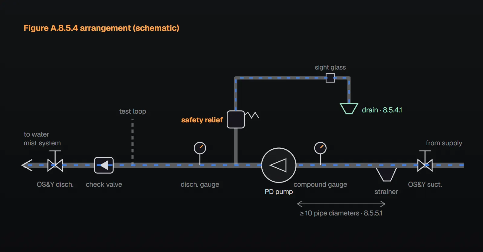
Figure A.8.5.4: typical piping
Figure A.8.5.4 in Annex A shows typical water mist pump piping from the supply to the system in this order:
- OS&Y suction isolation gate valve and suction strainer; at least 10 pipe diameters between the strainer and the pump suction port.
- 3½ in. (89 mm) compound suction gauge and the pump.
- Pipe tee and pressure relief valve at the pump discharge port; the acceptable relief flow return passes a sight glass.
- 3½ in. (89 mm) discharge gauge, test isolation valve and orifice plate test device on a flow test loop.
- Check valve, OS&Y discharge isolation gate valve and the water mist system.
Per the figure note, the relief return and the test loop are acceptable to plumb to drain, pump suction or supply; for return to suction the two conditions of 8.5.4.2 apply. Strainer, gauge and test rules are in 8.5 and 8.10.
8.3 versus 8.4
Per Annex A.3.3.52.19, the term “water mist positive displacement pumping unit” is not applied to individual pumps used to supply water mist systems. It applies to multi-pump systems in which pumps operate individually or in parallel based on downstream demand and the number of discharging nozzles, working together as a single unit. The 8.3 rules in this article are for water mist pumps; unit rules are in 8.4. Also, per Annex A.8.2.4, the 10-minute dry-run rule for foam pumps (8.2.4) does not apply to water mist pumps.
Common mistakes (from the sources)
- Treating an unloader valve as the safety relief valve: under 8.3.5 the unloader valve is in addition to the relief valve.
- Relief to suction without accounting for back pressure: 8.5.4.2(2) requires the valve and driver to be sized for suction back pressure; Annex A.8.5.4 asks for discharge-side backpressure to be considered.
- Relief to suction without overheating protection: 8.5.4.2(1); the Handbook suggests a circulation relief valve discharging to drain as a possible means.
Checklist
- Pump capacity meets the maximum system demand (8.3.1).
- Available NPSH exceeds required NPSH plus 5 ft (1.52 m) (8.3.2).
- Pump inlet pressure below the manufacturer’s recommended maximum (8.3.3).
- Unloader valve or orifice where pump output can exceed system flow (8.3.4).
- With an unloader valve, a listed safety relief valve per 8.5.2 is also provided (8.3.5).
- Relief to drain or to a water supply at atmospheric pressure; if to suction, overheating protection and valve and driver sized for suction back pressure (8.5.4).
- Backpressure on the relief discharge side considered (A.8.5.4).
Frequently Asked Questions
Can a centrifugal fire pump be used in a water mist system?
Per Annex A.8.3.1 the standard does not intend to prohibit stationary pumps. The NFPA 20 Handbook (2022) says a listed centrifugal fire pump meeting the system demand is permitted, while positive displacement pumps are more common because they can produce higher pressures.
What is an unloader valve and when is it needed?
A valve designed to relieve excess flow below pump capacity at set pump pressure (3.3.78.6). Where pump output can exceed the system flow requirement, a means such as an unloader valve or orifice is required (8.3.4).
Is a safety relief valve still needed with an unloader valve?
Yes. The unloader valve is in addition to the safety relief valve of 8.5.2 (8.3.5); under 8.5.2.1 every positive displacement pump has a listed safety relief valve.
Where does a water mist pump safety relief valve discharge?
To a drain or to a water supply at atmospheric pressure (8.5.4.1). Discharge into pump suction is permitted only with a means to prevent overheating and with the valve and driver sized for the suction back pressure (8.5.4.2).
Does the 10-minute dry-run rule for foam pumps apply to water mist pumps?
No. Per Annex A.8.2.4 the 10-minute dry-run requirement of 8.2.4 does not apply to water mist pumps.

SprinkCalc — Fire Sprinkler Design Across Three Standards
SprinkCalc covers hazard classification, design density and area, K-factor selection, water demand and hydraulic calculations for NFPA 13, FM Global and BS EN 12845 in a single iOS app, and exports a professional PDF report.
Download SprinkCalc on the App Store
MEP Calc — 110+ Engineering Calculators
MEP Calc bundles 110+ engineering modules in one iOS app: 21 fire calculations plus heating, cooling, HVAC, plumbing, steam and natural gas.
Download MEP Calc on the App StoreNFPA 20-2025, Standard for the Installation of Stationary Pumps for Fire Protection: 3.3.78.6, 8.3.1, 8.3.2, 8.3.3, 8.3.4, 8.3.5, 8.5.2.1, 8.5.4.1, 8.5.4.2; Annex A.3.3.52.19, A.8.2.4, A.8.3.1, A.8.5.4 and Figure A.8.5.4 (explanatory). NFPA 20 Handbook 2022 commentary: Sections 8.3 and 8.5.4.