Large fire pump motors can be supplied at 2.2 to 7.2 kV, and NFPA 20-2025 Section 10.6 sets separate rules for their controllers. The standard calls these “high-voltage” controllers in places; per the NFPA 20 Handbook (2022) commentary, the electrical industry treats them as medium-voltage. Per the Handbook, they are mostly full-voltage across-the-line starting types, can remove the need for a separate fire pump transformer, and come in much higher horsepower ratings than low-voltage units. General controller components are covered in fire pump controller components and starting and stopping in starting and stopping.
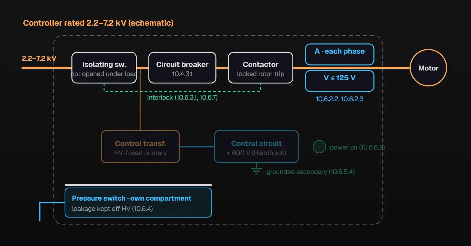
In short: controllers rated 2.2–7.2 kV follow Chapter 10 except as provided in 10.6.2 through 10.6.8 (10.6.1). Instead of the exterior metering rule (10.3.4.3), there is an ammeter for each phase and a voltmeter powered at not more than 125 V from a transformer (10.6.2). The isolating switch cannot be opened under load (10.6.3.1). The pressure switch is located so water leakage cannot reach high-voltage components (10.6.4). The control circuit is fed from a stepdown transformer with high-voltage fuses in each primary line (10.6.5.1). A contactor with current-limiting fuses may replace the circuit breaker; the fuses hold 600 percent of motor full-load current for at least 100 seconds and a spare set is kept in the controller (10.6.8).
Metering and testing (10.6.2)
10.3.4.3, which requires reading all line currents and voltages from the exterior, does not apply to these controllers (10.6.2.1). Instead the controller has an ammeter with a means of reading the current in each phase (10.6.2.2) and an indicating voltmeter, powered at not more than 125 V from a transformer connected to the motor supply, with a means of reading each phase voltage (10.6.2.3). Per the Handbook (2022), measuring inside equipment above 600 V carries a high shock risk; meters outside the enclosure and a voltmeter fed through a stepdown transformer isolate that voltage from the operator.
Disconnecting under load (10.6.3)
The isolating switch is prevented from being opened under load (10.6.3.1). A load-break disconnecting means may be used instead if its fault closing and interrupting ratings equal or exceed the installation’s requirements (10.6.3.2). Per the Handbook (2022), the isolating switch in these controllers is generally not rated to interrupt current, so it is interlocked with the contactor. The interlock must work both ways: the switch must not open a load, nor close onto a fault or the motor locked rotor current, or arcing and welding can result. If a switch can safely close on the available fault current and interrupt locked rotor current, no interlock is needed.
Pressure switch location (10.6.4)
The pressure-actuated switch required by 10.5.2.1 is located with special precautions so that water leakage cannot contact high-voltage components (10.6.4). Per the Handbook (2022), leakage onto high-voltage parts creates a shock risk for anyone touching the enclosure; the switch is normally at the bottom of the enclosure in a barriered compartment, and some designs use a separate enclosure with a sealed pass-through into the low-voltage compartment.
Low-voltage control circuit and indicators (10.6.5, 10.6.6)
| Rule | Clause |
|---|---|
| Control circuit fed from the high-voltage source through stepdown transformer(s) with high-voltage fuses in each primary line | 10.6.5.1 |
| Transformer supply interrupted when the isolating switch is open | 10.6.5.2 |
| Transformer secondary and control circuitry otherwise comply with 10.3.5 | 10.6.5.3 |
| One secondary line grounded unless all control and operator devices are rated for the high (primary) voltage | 10.6.5.4 |
| Secondaries of all current transformers in the high-voltage path grounded unless rated at the incoming line voltage | 10.6.5.5 |
| Indicators differ from 10.4.6; a visible indicator shows that power is available | 10.6.6.1, 10.6.6.2 |
| Indicator fed from the control transformer secondary (through resistors if needed) or a small stepdown transformer; a pilot lamp is accessible for replacement | 10.6.6.3, 10.6.6.4 |
Per the Handbook (2022), low voltage here means 600 V or less, which reduces shock risk for operators and maintenance staff. Interrupting the transformer when the switch is open keeps the contactor coil from closing the contacts and supplements the interlock against operating under load. A secondary line is grounded because control and operator devices are seldom rated for the primary voltage. The general rule in 10.3.5.2 allows an ungrounded secondary, but 10.6.5.4 is the exception for these controllers.
Protection of personnel (10.6.7)
Provisions, including such interlocks as might be needed, protect personnel from accidental contact with high voltage (10.6.7). Per the Handbook (2022), the equipment is built so high-voltage circuits are de-energized when the enclosure is opened, and intentional grounding may be needed to discharge any charge remaining on the motor circuit. It refers to NFPA 70E for electrical safety work practices.
Contactor and fuses instead of a circuit breaker (10.6.8)
A contactor with current-limiting motor circuit fuses may be used instead of the circuit breaker (disconnecting means) required by 10.4.3.1 if all of the following are met (10.6.8):
| Condition | Clause |
|---|---|
| Fuses mounted in the enclosure between the isolating switch and the contactor, interrupting the short-circuit current available at the controller input terminals | 10.6.8(1) |
| Interrupting rating adequate to provide the controller suitability rating (10.1.2.2) | 10.6.8(2) |
| Sized to hold 600 percent of motor full-load current for at least 100 seconds | 10.6.8(3) |
| A spare set of fuses of the correct rating kept in a compartment or rack within the enclosure | 10.6.8(4) |
Per the Handbook (2022), the 600 percent / 100 second sizing keeps the fuses from opening on a motor overload and coordinates with the locked rotor tripping curve. The spare set shortens the time the pump is out of service after a fuse opens; manufacturers supply the rack, but the fuses themselves are not necessarily supplied as standard. The Handbook gives 50 kA as a typical short-circuit rating for these controllers.
Locked rotor protection and emergency-run control (10.6.9, 10.6.10)
The locked rotor overcurrent device required by 10.4.4 may trip by opening the motor contactor coil circuit to drop out the contactor (10.6.9.1); the controller is restored to normal by an external manually reset device (10.6.9.2). The emergency-run handle complies with 10.5.3.2.1 and 10.5.3.2.2, except that mechanical latching can be automatic (10.6.10.1); with the contactor latched in, the locked rotor protection of 10.4.4 is not required (10.6.10.2). Per the Handbook (2022), in a fused controller the only way to de-energize the motor on overload is to open the contactor; manual reset keeps power from cycling back to the motor and retripping. With the contactor mechanically latched, overload protection is inoperative and only the fuses can de-energize the motor, which may take 100 seconds at 600 percent of full-load current.
Common field mistakes
- Opening the isolating switch under load, or no interlock: contrary to 10.6.3.1.
- Pressure switch above or beside high-voltage components: contrary to 10.6.4.
- Ungrounded control transformer secondary: contrary to 10.6.5.4 unless devices are rated for primary voltage.
- No spare fuse set: contrary to 10.6.8(4) in a contactor and fuse arrangement.
Checklist
- Ammeter per phase; voltmeter fed at not more than 125 V from a transformer (10.6.2.2, 10.6.2.3).
- Isolating switch–contactor interlock or suitable load-break means (10.6.3).
- Pressure switch separated from high voltage (10.6.4).
- Fused stepdown control transformer, supply cut by the isolating switch, grounded secondary and current transformers (10.6.5).
- Power-available indicator, replaceable pilot lamp (10.6.6).
- If fuses replace the breaker, all four conditions and a spare set (10.6.8).
- Locked rotor protection, external manual reset, emergency-run handle (10.6.9, 10.6.10).
Frequently Asked Questions
Is a circuit breaker mandatory in a medium-voltage fire pump controller?
No; a contactor with current-limiting motor circuit fuses may be used if four conditions are met: fuses between the isolating switch and contactor, adequate interrupting rating, holding 600 percent of full-load current for at least 100 seconds, and a spare set in the controller (10.6.8).
Can the isolating switch be opened under load?
No; provisions prevent it (10.6.3.1). A load-break disconnecting means with adequate fault closing and interrupting ratings is permitted instead (10.6.3.2). Per the Handbook (2022), the interlock must work both ways.
Where does the pressure switch go in the controller?
Located with special precautions so water leakage cannot contact high-voltage components (10.6.4). Per the Handbook (2022), it is usually at the bottom in a barriered compartment or in a separate enclosure with a sealed pass-through.
How is the voltmeter powered?
From a transformer connected to the motor supply, at not more than 125 V, with a means of reading each phase voltage; there is also an ammeter for each phase current (10.6.2.2, 10.6.2.3).
Does locked rotor protection work when the emergency-run handle is used?
With the contactor latched in, the locked rotor protection of 10.4.4 is not required (10.6.10.2). Per the Handbook (2022), only the fuses can then de-energize the motor.

SprinkCalc — Fire Sprinkler Design Across Three Standards
SprinkCalc covers hazard classification, design density and area, K-factor selection, water demand and hydraulic calculations for NFPA 13, FM Global and BS EN 12845 in a single iOS app, and exports a professional PDF report.
Download SprinkCalc on the App Store
MEP Calc — 110+ Engineering Calculators
MEP Calc bundles 110+ engineering modules in one iOS app: 21 fire calculations plus heating, cooling, HVAC, plumbing, steam and natural gas.
Download MEP Calc on the App StoreNFPA 20-2025, Standard for the Installation of Stationary Pumps for Fire Protection: 10.1.2.2; 10.3.4.3; 10.3.5, 10.3.5.2; 10.4.3.1; 10.4.4; 10.4.6; 10.5.2.1; 10.5.3.2.1, 10.5.3.2.2; 10.6.1; 10.6.2.1–10.6.2.3; 10.6.3.1, 10.6.3.2; 10.6.4; 10.6.5.1–10.6.5.5; 10.6.6.1–10.6.6.4; 10.6.7; 10.6.8(1)–(4); 10.6.9.1, 10.6.9.2; 10.6.10.1, 10.6.10.2. NFPA 20 Handbook 2022 commentary: Section 10.6.